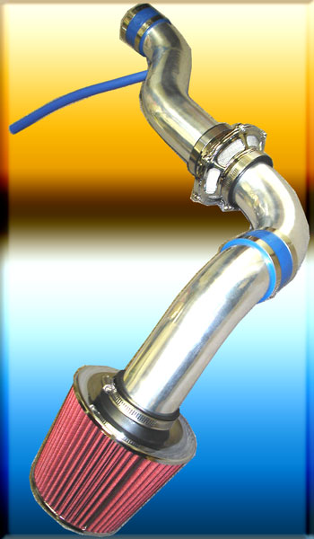
RTR Performance Cold Air Intake System
| The RTR Performance Cold Air Intake System is designed to position the air filter in the high-pressure area of the lower front valence of your vehicle.
While this ensures a supply of cold ambient air into the intake, it may if incorrectly installed allow the engine to ingest water and hydro-lock the engine, causing engine damage.
A bypass valve filter reduces this possibility and is highly recommended if not originally part if the kit.
To limit this possibility, ensure that the main filter is installed in such a manner that it is protected from water spray directly from the front and from below. Ensure that there are no openings in the panels that face directly towards the filter. It is also very important that the quality of the inner fender does not have any rips, tears or obvious holes that would allow wheel spray or snow from being deposited on the filter. Once installed, it is recommended that the filter be inspected visually after driving on a rainy/snowy day to insure that it is relatively dry and without any buildup of debris. There should also be no history of snow buildup in that area. It is recommended that the main filter be removed and cleaned with light soap and water every 6 months, this will keep the filter performing at peak performance. Once the system has been installed, make sure that the hose clamps that attach the pipes and filter together are completely secure and the filter should be resting several inches above the bottom of the bumper valance. Disclaimer! |
 |
| Installation Instructions | |
| Step 1. Remove the intake hose clamp from the Throttlebody, unclip the filter snaps on the intake filter box. Unplug the hose from the Valve cover, then remove that part of the filter assembly. Remove the 4 bolts holding the remaining portion of the filter box assembly, then pull that part of the box out. | |
| Step 2. Remove the remaining ducting hose from the filter box to the fender well from the engine bay. | |
| Step 3. Remove the battery so that the battery tray hole is exposed. This hole may need to be widened depending on vehicle year and the diameter of the Aluminum piping. Test fit the aluminum pipe to check clearance. A tight fit is preferred to reduce movement. | |
| Step 4. Jack the car up securely and remove the driver's side front tire. | |
| Step 5. Unscrew the screws holding the splash shield to the fender assembly so that you can gain access to the lower intake resonator. Once there, remove the 2-3 bolts holding the resonator in place, then remove the lower intake resonator assembly. | |
| Step 6. Install the Aluminum pipe with the silicone coupler to the throttlebody and tighten the hose clamps. Install the supplied silicone hose to the Valve cover with the supplied hose clamp, then insert the other end to the aluminum pipe, secure with the remaining hose clamp. You may want to trim the length of the silicone hose for a custom fit. If cut, it is recommended that some slack be left in it for expansion/contraction due to temperature changes. | |
| Step 7. If ordered, insert the bypass filter and tighten the hose clamp. Next, install the shorter right-angle aluminum pipe to the other end of the bypass filter and tighten the hose clamp. | |
| Step 8. Insert the last remaining aluminum pipe through the battery tray hole, then attach the two aluminum pipes together with the silicone coupler, and tighten the two hose clamps. | |
| Step 9. Install the main cone filter on the end of the aluminum pipe from under the car. Make sure that the hose clamp is secure and aligned properly to insure a proper seal. At this point, make sure that all of the aluminum/silicone hose connections are secure and tight. | |
| Step 10. Reinstall the lower splash guard and tire, then lower the car. | |
| Step 11. Reinstall the battery. You will need to slide the battery slightly to the side to clear the aluminum pipe. If you have an oversized/heavy-duty battery, you may run into clearance issues. To remedy this, you can relocate the ignition coil to the chassis, 6-8" away. This is an easy modification to perform as there are many available bolt threads on the chassis way to bolt the coil to. | |
| Step 12. Do a quick check of everything and confirm that everything is installed properly, and that there are no tools left in the engine bay. Start the car and monitor to make sure everything is working properly. |